- 1 Network Layer: overview
- [[#1 Network Layer: overview#1.1 Router|1.1 Router]]
- [[#1 Network Layer: overview#1.2 Network layer functions|1.2 Network layer functions]]
- [[#1 Network Layer: overview#1.3 Data Plane|1.3 Data Plane]]
- [[#1 Network Layer: overview#1.4 Control Plane|1.4 Control Plane]]
- [[#1 Network Layer: overview#1.5 Network service Model|1.5 Network service Model]]
- [[#1.5 Network service Model#1.5.1 Internet “Best Effort” Service Model|1.5.1 Internet “Best Effort” Service Model]]
- [[#1.5 Network service Model#1.5.2 Table|1.5.2 Table]]
- 2 Inside a Router
- [[#2 Inside a Router#2.1 Ports and Switching|2.1 Ports and Switching]]
- [[#2.1 Ports and Switching#2.1.1 Input port functions|2.1.1 Input port functions]]
- [[#2.1 Ports and Switching#2.1.2 Destination-Based Forwarding|2.1.2 Destination-Based Forwarding]]
- [[#2 Inside a Router#2.2 Switching Fabrics|2.2 Switching Fabrics]]
- [[#2.2 Switching Fabrics#2.2.1 Switching via memory|2.2.1 Switching via memory]]
- [[#2.2 Switching Fabrics#2.2.2 Switching via bus|2.2.2 Switching via bus]]
- [[#2.2 Switching Fabrics#2.2.3 Switching via interconnection network|2.2.3 Switching via interconnection network]]
- [[#2 Inside a Router#2.3 Input port Queueing|2.3 Input port Queueing]]
- [[#2 Inside a Router#2.4 Output port Queueing|2.4 Output port Queueing]]
- [[#2.4 Output port Queueing#2.4.1 Buffer management|2.4.1 Buffer management]]
- [[#2 Inside a Router#2.5 Packet Scheduling|2.5 Packet Scheduling]]
- [[#2.5 Packet Scheduling#2.5.1 FCFS|2.5.1 FCFS]]
- [[#2.5 Packet Scheduling#2.5.2 Priority|2.5.2 Priority]]
- [[#2.5 Packet Scheduling#2.5.3 Round Robin|2.5.3 Round Robin]]
- [[#2.5 Packet Scheduling#2.5.4 Weighted fair queueing|2.5.4 Weighted fair queueing]]
- [[#2 Inside a Router#2.1 Ports and Switching|2.1 Ports and Switching]]
- 3 IP: the internet protocol
- [[#3 IP: the internet protocol#3.1 IP Datagram format|3.1 IP Datagram format]]
- [[#3.1 IP Datagram format#3.1.1 Fragmentation|3.1.1 Fragmentation]]
- [[#3 IP: the internet protocol#3.2 Addressing|3.2 Addressing]]
- [[#3.2 Addressing#3.2.1 Subnets|3.2.1 Subnets]]
- [[#3.2 Addressing#3.2.2 Classless InterDomain Routing (CIDR)|3.2.2 Classless InterDomain Routing (CIDR)]]
- [[#3.2 Addressing#3.2.3 How to obtain an IP address|3.2.3 How to obtain an IP address]]
- [[#3.2 Addressing#3.2.4 Reflection on IPv4|3.2.4 Reflection on IPv4]]
- [[#3 IP: the internet protocol#3.3 Network Address Translation|3.3 Network Address Translation]]
- [[#3.3 Network Address Translation#3.3.1 Implementation|3.3.1 Implementation]]
- [[#3.3 Network Address Translation#3.3.2 NAT controversy|3.3.2 NAT controversy]]
- [[#3 IP: the internet protocol#3.4 IPv6|3.4 IPv6]]
- [[#3.4 IPv6#3.4.1 IPv6 datagram format|3.4.1 IPv6 datagram format]]
- [[#3 IP: the internet protocol#3.5 Transition from IPv4 to IPv6|3.5 Transition from IPv4 to IPv6]]
- [[#3.5 Transition from IPv4 to IPv6#3.5.1 Tunneling|3.5.1 Tunneling]]
- [[#3.5 Transition from IPv4 to IPv6#3.5.2 IPv6 Adoption|3.5.2 IPv6 Adoption]]
- [[#3 IP: the internet protocol#3.6 ARP: Address Resolution Protocol|3.6 ARP: Address Resolution Protocol]]
- [[#3.6 ARP: Address Resolution Protocol#3.6.1 How to get a resolution pair|3.6.1 How to get a resolution pair]]
- [[#3 IP: the internet protocol#3.7 ICMP protocol|3.7 ICMP protocol]]
- [[#3.7 ICMP protocol#3.7.1 ICMP messages|3.7.1 ICMP messages]]
- [[#3 IP: the internet protocol#3.1 IP Datagram format|3.1 IP Datagram format]]
- 4 Generalized Forwarding, SDN
- [[#4 Generalized Forwarding, SDN#4.1 Flow Table Abstraction|4.1 Flow Table Abstraction]]
- [[#4.1 Flow Table Abstraction#4.1.1 OpenFlow Protocol|4.1.1 OpenFlow Protocol]]
- [[#4.1 Flow Table Abstraction#4.1.2 OpenFlow abstraction|4.1.2 OpenFlow abstraction]]
- [[#4 Generalized Forwarding, SDN#4.1 Flow Table Abstraction|4.1 Flow Table Abstraction]]
- 5 Middleboxed
- 6 IP hourglass
- [[#6 IP hourglass#6.1 Internet’s middle age: ~55 years (since ‘69)|6.1 Internet’s middle age: ~55 years (since ‘69)]]
- 7 Where’s the intelligence
uni
Let’s now introduce the concept of Internetwork.
Understand principles behind network layer services
- service models
- forwarding versus routing
- how a router works
- addressing
- generalized forwarding
- Internet architecture
Instantiation and implementation in the internet
- IP protocol
- NAT, middleboxes
1 Network Layer: overview
This layer receives from the transport layer and transports a segment from the sending to the receiving host.
The sender encapsulates segments into datagrams and passes them to the link layer.
The receiver delivers these segments to the transport layer protocol.
1.1 Router
Routers only implement physical layer, link layer and network layer.
A router examines the header fields in all IP datagrams that pass through it and according to these fields it moves these datagram from input ports to the correct output ports.
1.2 Network layer functions
- forwarding: move packets from a router’s input link to the appropriate router output link.
- routing: determine the route taken by the packets from source to destination
- routing algorithms
These are two separate things, both done by routers.
1.3 Data Plane
The data plane determines how a datagram arriving in one of the router’s input ports to an output port → forwarding
1.4 Control Plane
The control plane determines how a datagram is routed among routers → routing
There are two control-plane approaches:
- traditional routing algorithms: individual routing algorithm components in each router
- software-defined networking (SDN): implemented in (remote) servers: the forwarding tables are filled by the servers, not by the routers. This is a more modern approach.
The control plane fills the forwarding table, and the data plane utilizes it.
1.5 Network service Model
Service can be offered for individual datagrams, or for a flow of datagrams.
1.5.1 Internet “Best Effort” Service Model
This is the service model offered by the IP protocol, it does NOT guarantee:
- successful datagram delivery
- timing or order of delivery
- bandwidth available for datagram flow
This works because we have so much available bandwidth so it is never a problem.
This was chosen because it is easy, and given enough bandwidth, it works.
1.5.2 Table
Quality of Service (QoS) guarantees:
| Network architecture | Service Model | Bandwidth | Loss | Order | Timing |
|---|---|---|---|---|---|
| Internet | best effort | none | no | no | no |
| ATM | Constant Bit rate | constant rate | yes | yes | yes |
| ATM | Available Bit rate | guaranteed min | no | yes | no |
| Internet | Intserv Guaranteed (RFC 1633) | yes | yes | yes | yes |
| Internet | Diffserv (RFC 2475) | possible | possibly | possibly | no |
2 Inside a Router
The routing processor is responsible for the control plane (software), it operatore in a timeframe of milliseconds.
The high-speed switching fabric is responsible for the data plane (hardware), it operates in a timeframe of nanoseconds.
2.1 Ports and Switching
2.1.1 Input port functions
router input port:

- destination-based forwarding: the forward is based only on the destination IP address (traditional)
- generalized forwarding: the forward is based on any set of header field values
2.1.2 Destination-Based Forwarding
Longest Prefix Matching
When looking for the entry of the forwarding table for a given destination address, we use the longest address prefix that matches the destination address.
This is often performed using ternary content addressable memories (TCAMs):
- present the address to TCAM and in one clock cycle retrive the address, regardless of table size.
2.2 Switching Fabrics
The switching Fabrics transfer a packet from an input link to the appropriate output link.
The switching rate is the rate at which packets can be transferred from inputs to outputs, it is often measured as a multiple of the input/output line rate (rate R).
There are 3 types of switching fabrics:
2.2.1 Switching via memory
The switching is under direct control of the CPU. The packet is copeid to the system’s memory. The speed is limited by the memory bandwidth
2.2.2 Switching via bus
Bus contention: the switching spped is limited by the bus bandwidth. A 32 Gbps bus is sufficient for access routers.
2.2.3 Switching via interconnection network
This utilizes a crossbar, instead of a single bus we have a matrix of buses.
We can even stack planes of matrixes.
This can make good use of parallelism:
- the datagram is fragmented into cells of fixed length
- the cells are switched through the fabric and reassembled into the datagram at the exit.
2.3 Input port Queueing
If the switching fabric is slower than the input ports combined, queueing may occur → queueing delay and loss due to buffer overflow.
Head of line (HOL) blocking: the queued datagram at the front of the queue prevents others in the queue from moving forward.
2.4 Output port Queueing
Buffering happens when datagrams arrive from the fabric faster thank the link transmission rate.
The drop policy determines which datagrams to drop if there are no free buffers.
The scheduling discipline chooses among the queued datagrams for transmission → priority scheduling.
Output queueing is a syndrome of congestion.
2.4.1 Buffer management
-
tail drop: drop the arriving packet
-
priority: drop on priority basis
-
marking: which packets to mark to signal the congestion (ECN, RED)
2.5 Packet Scheduling
Deciding which packet to send next on the link.
2.5.1 FCFS
2.5.2 Priority
The arriving traffic is classified and queued by class. Inside a priority queue, FCFS is used. It is always sent a packet from the currently not empty highest priority queue.
2.5.3 Round Robin
The arriving traffic is classified and queued by class.
2.5.4 Weighted fair queueing
This is a generalized Round Robin, where the queues are not handled the same. Every queue has a weight, that determines it’s percentage of traffic available.
See Network Neutrality.
3 IP: the internet protocol
This is one of the protocols that we can find at the network layer.
The IP protocol uses as support the 3.7 ICMP protocol: this handles error reporting and router signaling.
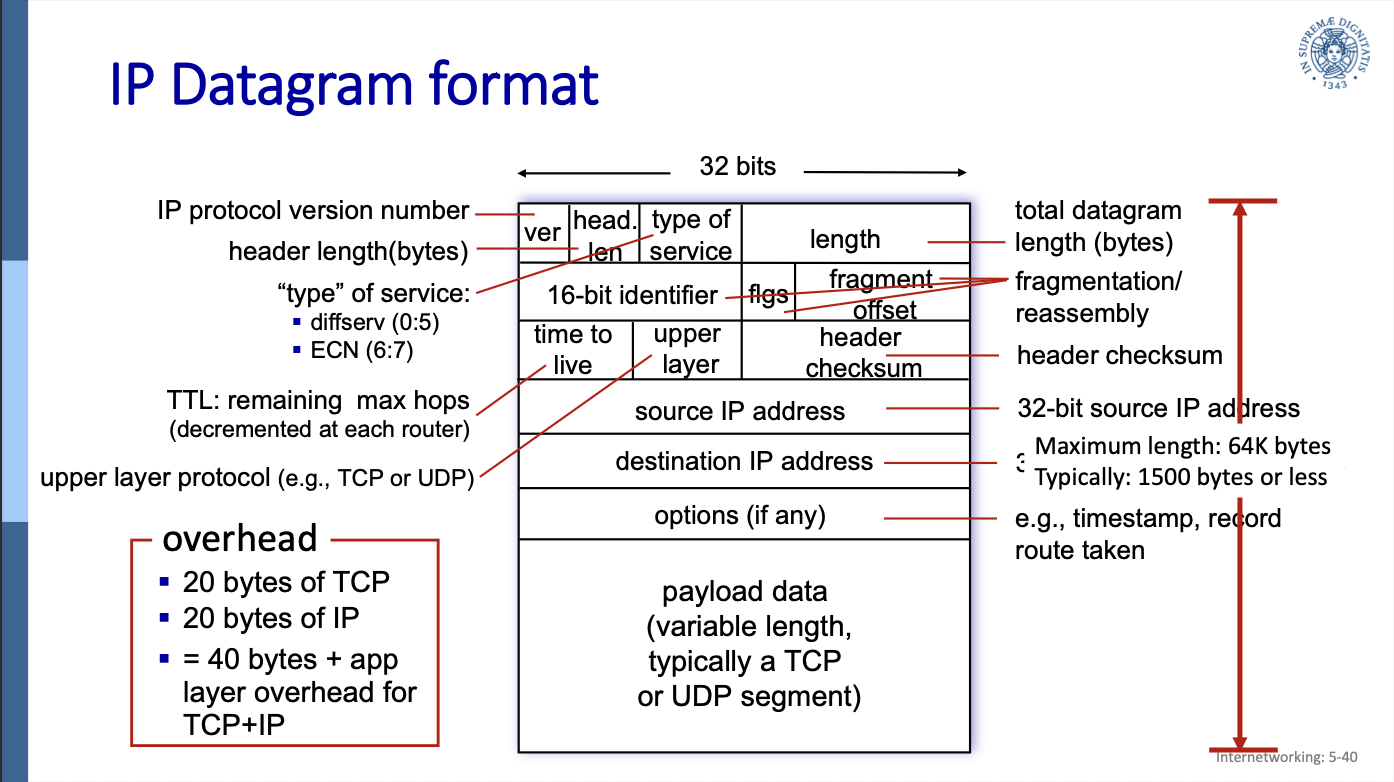
3.1 IP Datagram format
-
ver: the still most used version is the IP protocol version 4. In this field we always have to write 4.
-
header length in bytes
-
type of service (ToS)
- bits 0 to 5 represent diffserv: the priority
- bits 6 and 7 are used for ECN (not really used) (see 4.6.5 ECN explicit congestion notification)
- TTL: time to live, maximum number of forwards in routers before being dropped. It is decremented at each router.
-
length (16 bit: totale length of the datagram
-
upper layer protocol (the upper layer is the transport layer)
-
header checksum
-
source comes before destination because it isn’t like in the data link, where if the destination doesn’t match, the message is not listened to.
-
fragment offset (13 bit): the offset of the first segment in the original datagram
-
fragflag=1 means the current datagram is NOT the last fragment
overhead:
- 20 bytes of TCP
- 20 bytes of IP
- this gives a total of 40 bytes of overhead + any application layer overhead for TCP+IP
3.1.1 Fragmentation
A large datagram is fragmented in smaller datagrams and gets only reassembled at the final destination.
This is necessary because network links have an MTU (maximum transfer unit): the largest possible link-level frame.
Different link types have different MTUs.
If not every fragment arrives in a determined timeframe, every fragment is dropped → lost datagram.
If the next link has a smaller MTU, it has to again fragment the fragments.
Fragmenting a 4000 bytes datagram for an MTU of 1500 bytes
- length=1500 (1480 bytes in data field) ID=x fragflag=1 offset=0
- length=1500 ID=x fragflag=1 offset=1480/8=185
- length=1040 ID=x fragflag=0 offset=370
3.2 Addressing
This is a 32-bit identifier associated with each interface of a host or router.
An interface is a connection between a host/router and the physical link.
dotted-decimal IP address notation:
223.1.1.1 = 11011111 00000001 00000001 00000001
3.2.1 Subnets
A subnet is:
- a network of interface that can physically reach each oter without passing through an intervening router
- a network of interfaces that have in common the first high order bits of the IP address.
subnet mask: used to identify the subnet(s) of an address:
- subnet mask: /24 : the high order 24 bits of the address identify the subnet part of the IP address
mask: /24 = 11111111 11111111 11111111 00000000
IP address Classes (IPv4)
- A = 8bits (subnet) + 24bits (host)
- B = 16+16
- C = 24+8
- D x multicast
- E x scopi futuri
These are not enough IPv4 addresses, and a lot of addresses are not used because of the classes.
3.2.2 Classless InterDomain Routing (CIDR)
The idea is the same, but now there are no classes and the address format is: where is the number of bit in the subnet portion.
3.2.3 How to obtain an IP address
Getting an IP address consists of two parts:
- how does an host get an IP address within its network
- how does a network get an IP address for itself
How a Host gets an IP address
For a Host an IP address is either:
- hard-coded by the sysadmin in the config file (in UNIX /etc/rc.config)
- DHCP
How a network gets a subnet
A network gets an allocated portion of its provider ISP’s address space.
For example an ISP has this block of addresses:
11001000 00010111 00010000 00000000 : 200.23.16.0/20
The ISP then allocates its address space in 8 blocks:
- 11001000 00010111 0001.0000 00000000
- 11001000 00010111 0001.0010 00000000
- 11001000 00010111 0001.0100 00000000
…
8. 11001000 00010111 0001.1110 00000000
Normally though the ISP would’t fragment its address space in equal blocks, since different organization have different needs for addresses.
How an ISP gets a block of addresses
The ICANN (Internet Corporation for Assigned Names and Numbers) allocates IP addresses, through 5 regional registries (RRs), who may then allocate to local registries.
The ICANN also manages the DNS root zone, including the delegation of individual TLD (top level domain) management.
3.2.4 Reflection on IPv4
ICANN allocated the last chunk of IPv4 addresses to RRs in 2011…
NAT helps IPv4 address space exhaustion.
IPv6 has a 128 bit (instead of 32) address space.
3.3 Network Address Translation
With NAT all devices in a local network share just one IPv4 address from the outside world point of view.
This means every datagram that leaves a local network has the same source NAT IP address, but different source port numbers.
Every device in a local network has a 32 bit address in a “private” IP address space, that can only be used in the local network, since these private IP address spaces only work in the local network and don’t comunicate with the outer internet.
These private IP address spaces are:
- 10/8
- 172.16/12
- 192.168/16
Advantages:
- all devices in a local network use ONE IP address
- can change ISP without changing addresses of devices in a local network
- security: devices inside a local network are not directly accessible by the outside world
3.3.1 Implementation
The NAT router must now keep a NAT translation table.
It must transparently:
- replace every source IP address and port number of every outgoing datagram to the NAT IP address and new port number
- remember every (source IP address, port number) to (NAT IP address, new port number) translation pair.
- for the incoming datagrams perform the inverse translation.
NAT translation table:
| WAN address | LAN address |
|---|---|
| 138.76.29.7, 5001 | 10.0.0.1, 3345 |
| 138.76.29.7, … | 10. … , … |
3.3.2 NAT controversy
- routers should only process up to layer 3, instead it changes things from layer 4, address and port
- address shortage should be solved by IPv6
- violates end-to-end argument, information should be exchanged end-to-end, nobody in the middle should change this information, instead the router does
- NAT traversal: what if a client wants to connect to server behind NAT? → Port Forwarding: we have to insert manually a line in the NAT table, binding every (NAT address , port xx) to (server’s LAN address, port yy). So every request from outside coming for port xx, goes directly to the server, port yy.
3.4 IPv6
Why not IPv5? It was already taken by “string protocol”, but it failed.
This was introduced because 32 bits are not enough (IPv6 uses 128 bits) and an additional motivation was to speed up processing/forwarding: instead of a variable length header with IPv6 we can use a 40 byte fixed length header. Also this enables different network-layer treatment of “flows”.
3.4.1 IPv6 datagram format
IPv6 datagram format:
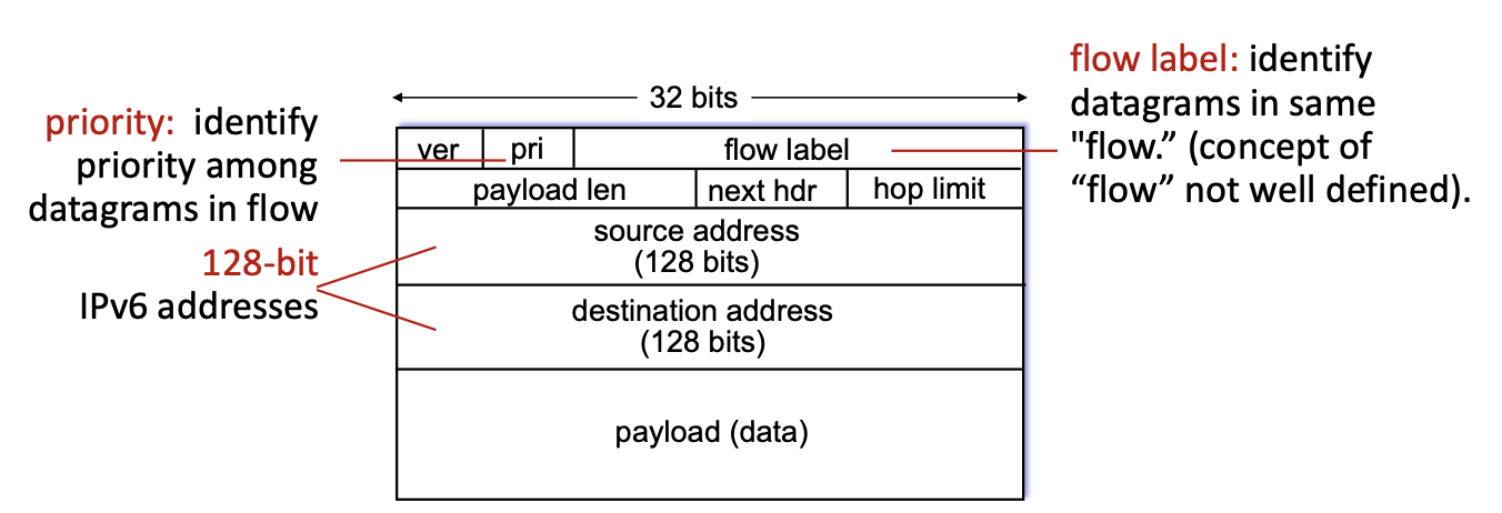
- flow label: this identifies to which “flow” a datagram belongs
- pri: this indicated the priority of this datagram inside its flow
- hop limit: this is a different name for the TTL field, works exactly the same
- next hdr: in IPv4 we had a field that indicated the upper layer protocol, this is the same thing: inside the payload there is the header for the transport layer protocol, the “next header” field indicates what this header inside the payload is
the following is missing compared to IPv4:
- no checksum (to speed up processing): at every “hop” the checksum must be recomputed because the TTL (hop limit) gets decreased by one.
- no fragmentation: if a datagram is to big for this link, it gets discarded, we need to introduce a new message for “datagram too big”, to notify sender → need to make new 3.7 ICMP protocol, version 6, to introduce these new messages.
For IoT we introduce a new kind of fragmentation, because these links have really low MTUs. - no options: in IPv6 we now have a fixed length header!
3.5 Transition from IPv4 to IPv6
This transition has been going on for ~25 years: we cannot upgrade every router at once, how can the internet continue working with these two protocols coexisting?
3.5.1 Tunneling
The real answer is tunneling: the IPv6 datagram gets carried as a payload in a IPv4 datagram among IPv4 routers (“packet within a packet”).
Tunneling is also extensively used in other contexts (4G, 5G).
Encapsulation
There are special routers that are split in 2, on side receives IPv6 packets, one side send IPv4 packets.
The IPv6 part receives a packet, extrapolates the data needed for building the IPv4 header, and passes the entire packet as the payload and the data for routing to the IPv4 part, which then builds the IPv4 packet and sends it forward.
3.5.2 IPv6 Adoption
Google has estimated that ~45% of their clients access their services via IPv6 (as of 3 November 2024) (it was ~30% in 2020), worldwide data.
This data is very different by country though.
NIST says ~1/3 of all US government domains are IPv6 capable.
3.6 ARP: Address Resolution Protocol
An ARP table is a table containing {MAC address , IP address} pairs of translation.
Each IP node (host, router) has an ARP table.
ARP table:
| IP address | MAC address | TTL |
|---|---|---|
| ip address | mac address | Time after which the address mapping will be forgotten (typically 20min) |
3.6.1 How to get a resolution pair
ARP: on the same LAN
If the sender doesn’t have the receiver’s MAC address in its ARP table, it broadcasts an ARP query packet, containing the receiver’s IP address.
All the hosts on the LAN receive this ARP packet, receiver included, which replies to the sender with its MAC address, and the frame is finally sent.
The sender caches this IP-to-MAC pair in its ARP table, until this information becomes old (times out).
soft state: information times out unless refreshed.
ARP is “plug and play”: the nodes create their ARP tables without intervention from the network’s administrator.
ARP: routing to another LAN
Walkthrough:
A wants to send a datagram to B, passing per router R.
Routers have a different ARP table for every LAN they connect to.
A creates IP datagram with source A, destination B
A uses ARP to get R’s MAC address for 111.111.111.110
A creates link-layer frame with R’s MAC address as dest, frame contains A-to-B IP datagram
A’s NIC sends frame
R’s NIC receives frame
R removes IP datagram from Ethernet frame, sees its destined to B
R uses ARP to get B’s MAC address
R creates frame containing A-to-B IP datagram sends to B
3.7 ICMP protocol
This protocol is used by hosts and routers to communicate network-level information.
The ICMP protocol is above the IP protocol: ICMP messages are carried in IP datagrams.
But the IP protocol as well heavily relies on the ICMP protocol.
3.7.1 ICMP messages
The ICMP messages contain:
- type
- code
- header + first 8 bytes of IP datagram causing the error
| Type | Code | Description | notes |
|---|---|---|---|
| 0 | 0 | echo reply (ping) | |
| 3 | 0 | dest. network unreachable | |
| 3 | 1 | dest host unreachable | |
| 3 | 2 | dest protocol unreachable | |
| 3 | 3 | dest port unreachable | |
| 3 | 6 | dest network unknown | |
| 3 | 7 | dest host unknown | |
| 4 | 0 | source quench (not used) | not used anymore: used for rate control, for congestion (“you are going to fast, I’m gonna lose packets!“) |
| 8 | 0 | echo request (ping) | |
| 9 | 0 | route advertisement | |
| 10 | 0 | router discovery | router announces itself as router |
| 11 | 0 | TTL expired | when TTL (hop limit) expires |
| 12 | 0 | bad IP header | IP header can get corrupted → checksum fails |
4 Generalized Forwarding, SDN
What we have seen until now can be named “Destination Based Forwarding”: the only thing it cares about is the destination IP address.
Using the forwarding table is a “match plus action” approach.
While still using a “match plus action” approach, we can instead of looking only at the destination IP address and therefore routing, use every information included in a datagram and take different actions:
- drop
- copy
- modify
- log
So now the matching is now made on more information, and there are more actions possible.
4.1 Flow Table Abstraction
To implement this new approach we can’t use the forwarding table anymore, we need a new table: the flow table.
- Flow: defined by the values in the header
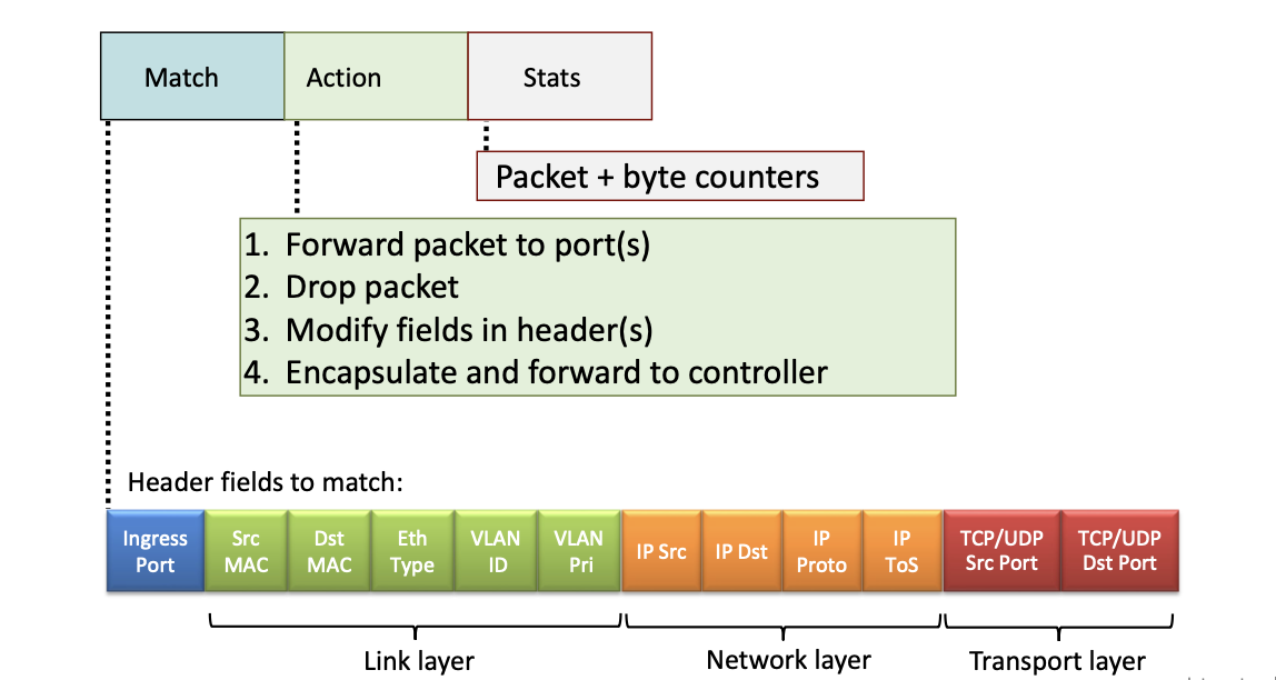
- Generalized forwarding: simple packet handling rules:
- match: pattern values in the packet’s header fields
- actions: actions to take on matched packets: drop, forward, modify or send to controller
- priority: disambiguate overlapping patterns
- counters:
#bytesand#packets
Flow table:
| match | action |
|---|---|
src=*.*.*.*, dest=3.4.*.* | forward(2) |
src=1.2.*.*, dest=*.*.*.* | drop |
src=10.0.0.3, dest=*.*.*.* | send to controller |
- a controller is a special device that can analyze packets and find out if they are malicious
4.1.1 OpenFlow Protocol
One of the protocols to implement this generalized forwarding is OpenFlow.
This is how an OpenFlow Table entry is composed:
OpenFlow examples
- destination based forwarding:
- specified fields:
- IP dst xx
- Action: forward to port xx
- specified fields:
- firewall:
-
specified fields:
- TCP dst port xx
-
action: drop
-
specified fields:
- IP src
-
action: drop
-
4.1.2 OpenFlow abstraction
This match+action abstraction unifies different kinds of devices:
| device | match | action |
|---|---|---|
| router | longest destination IP prefix | forward out a link |
| switch | destination mac address | forward of flood |
| firewall | IP addresses and TCP/UDP port numbers | permit or deny |
| NAT | IP address and port | rewrite address and port |
5 Middleboxed
RFC 3234: “middlebox: any intermediary box performing functions apart from normal, standard functions of an IP router on the data path between a source host and destination host”.
From this definition these are middleboxes:
- caches
- load balancers
- firewalls, IDS
- NAT
- application specific
- ecc..
Middleboxes were initially proprietary hardware solutions, now there are programmable middleboxes: middleboxes that expose APIs.
We are moving towards programmable networks.
Software defined networking (SDN): software-programmable networks.
6 IP hourglass
- http, smtp, rtp, quic, dash, …
- TCP, UDP
- IP
- ethernet, PPP, PDCP, WiFi, bluetooth
- copper, radio, fiber
Internet’s thin waist: there is only one network layer protocol: 3 IP the internet protocol.
6.1 Internet’s middle age: ~55 years (since ‘69)
Now there are middleboxes operating inside the network:
- NAT
- caching
- NFV
- firewalls
- and still IP
7 Where’s the intelligence
- Traditional phone net: intelligence and computing are in the center, at the network switches
- Internet (pre 2005): intelligence and computing are at the edge
- Internet (post 2005): now we have programmable network devices, intelligence and computing are both at the network switches and at the edge.