- 1 Context
- 2 Introduction
- [[#2 Introduction#2.1 Elements of a wireless network|2.1 Elements of a wireless network]]
- [[#2 Introduction#2.2 Characteristics of different wireless links|2.2 Characteristics of different wireless links]]
- [[#2 Introduction#2.3 Classification of Wireless Networks|2.3 Classification of Wireless Networks]]
- [[#2.3 Classification of Wireless Networks#2.3.1 Wireless Network Taxonomy|2.3.1 Wireless Network Taxonomy]]
- 3 Wireless
- [[#3 Wireless#3.1 Wireless Links and network characteristics|3.1 Wireless Links and network characteristics]]
- [[#3 Wireless#3.2 Wireless LANs: 802.11: WiFi|3.2 Wireless LANs: 802.11: WiFi]]
- [[#3.2 Wireless LANs: 802.11: WiFi#3.2.1 WLAN Architecture (7.3.1)|3.2.1 WLAN Architecture (7.3.1)]]
- [[#3.2 Wireless LANs: 802.11: WiFi#3.2.2 802.11 AP association|3.2.2 802.11 AP association]]
- [[#3.2 Wireless LANs: 802.11: WiFi#3.2.3 Multiple Access|3.2.3 Multiple Access]]
- [[#3.2 Wireless LANs: 802.11: WiFi#3.2.4 Collisions|3.2.4 Collisions]]
- [[#3.2 Wireless LANs: 802.11: WiFi#3.2.5 the 802.11 Frame (7.3.3)|3.2.5 the 802.11 Frame (7.3.3)]]
- [[#3.2 Wireless LANs: 802.11: WiFi#3.2.6 Mobility within the same subnet|3.2.6 Mobility within the same subnet]]
- [[#3.2 Wireless LANs: 802.11: WiFi#3.2.7 Advanced Capabilities (7.3.5)|3.2.7 Advanced Capabilities (7.3.5)]]
- [[#3 Wireless#3.3 Wireless LANs: LiFi: Light Fidelity|3.3 Wireless LANs: LiFi: Light Fidelity]]
- [[#3 Wireless#3.4 Wireless PANs: Bluetooth (7.3.6)|3.4 Wireless PANs: Bluetooth (7.3.6)]]
- [[#3 Wireless#3.5 Cellular networks: 4G and 5G (7.4)|3.5 Cellular networks: 4G and 5G (7.4)]]
- [[#3.5 Cellular networks: 4G and 5G (7.4)#3.5.1 Elements of the 4G LTE architecture (7.4.1) GUARDA LIBRO|3.5.1 Elements of the 4G LTE architecture (7.4.1) GUARDA LIBRO]]
- [[#3.5 Cellular networks: 4G and 5G (7.4)#3.5.2 LTE mobiles: sleep modes|3.5.2 LTE mobiles: sleep modes]]
- [[#3.5 Cellular networks: 4G and 5G (7.4)#3.5.3 5G|3.5.3 5G]]
- 4 Mobility (7.5)
- [[#4 Mobility (7.5)#4.1 Approaches to mobility|4.1 Approaches to mobility]]
- [[#4 Mobility (7.5)#4.2 Cellular Networks|4.2 Cellular Networks]]
- [[#4 Mobility (7.5)#4.3 ISP/WiFi Networks|4.3 ISP/WiFi Networks]]
- [[#4 Mobility (7.5)#4.4 Mobility management|4.4 Mobility management]]
- [[#4.4 Mobility management#4.4.1 Mobility with indirect routing|4.4.1 Mobility with indirect routing]]
- [[#4.4 Mobility management#4.4.2 Mobility with direct routing|4.4.2 Mobility with direct routing]]
- [[#4 Mobility (7.5)#4.5 Mobility: impact on higher-layer protocols|4.5 Mobility: impact on higher-layer protocols]]
#uni
1 Context
There are much more wireless phone subscribers than wired phone subscribers.
The are much more mobile-broadband-connected devices than fixed-broadband-connected devices.
We need to face two different challenges:
- wireless: communication over wireless link
- mobility: handling the mobile user who changes point of attachment to the network
2 Introduction
2.1 Elements of a wireless network
- Wireless Hosts
- laptop, smartphone, IoT
- these run applications
- these may be stationary (non-mobile) or mobile
- wireless does not always mean mobility! (a laptop that never leaves the office but is connected via wifi is wireless but not mobile)
- Base Station / Wifi Access Points (these are Link Layer Devices)
- these are typically connected to the wired network
- these are a relay: they are responsible for sending packets between the wired network and the wireless hosts in its “area”
- Wireless Link
- they are typically used to connect mobile users to the base stations
- multiple access protocol coordinate the link access
- various transmission rates, distances and frequency bands
2.2 Characteristics of different wireless links
Different wireless Links have different characteristics, link bandwidth and range: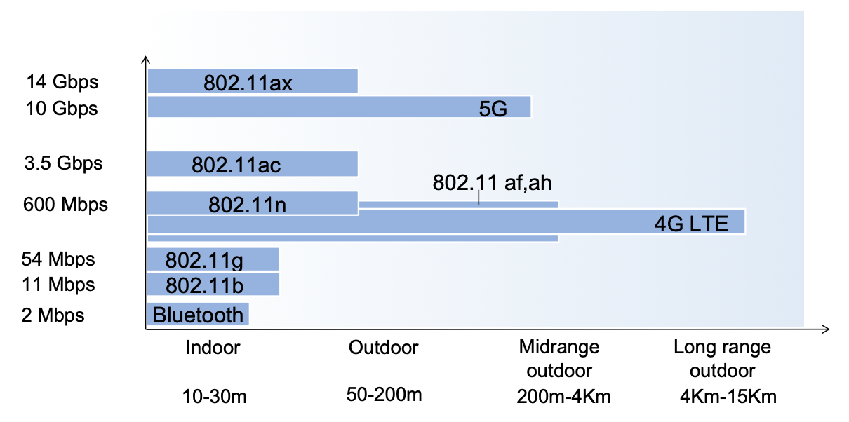
- WiFi is the commercial name for the 802.11 technology
- Bluetooth is the commercial name for the 802.15.1 technology: short range, low energy, “high” (lol) bandwidth
- 802.15.4 is short range, low energy and low bandwidth
2.3 Classification of Wireless Networks
There are different classes of wireless networks:
- Infrastructured Mode:
- the base station connects mobiles into a wired network
- handoff: mobiles when moving change the base station providing connection into the wired network, the change is called handoff
- Ad hoc Mode:
- no base stations
- nodes can only transmit to other nodes within link coverage
- nodes organize themselves into a network and route among themselves
2.3.1 Wireless Network Taxonomy
| Single Hop | Multiple Hops | |
|---|---|---|
| Infrastructure-based | Host connects to base station which connects to the larger internet: WiFi, cellular networks | Host may have to relay through several wireless nodes to connect to the larger internet: |
| No base station, no connection to the larger internet: | No base station, no connection to larger internet. May have torelay each other a given wireless node: |
3 Wireless
3.1 Wireless Links and network characteristics
Wireless brings important differences from wired links:
- decreased signal strength: radio signal attenuates asi it propagates through matter (path loss)
- interference from other sources: wireless network frequencies get shared by many devices
- multipath propagation: radio signal reflects off objects
- SNR1: signal to noise ratio: the bigger the easier to extract signal from noise
- SNR versus BER2 (Bit Error Rate) tradeoffs:
- if given the physical layer: increasing power increases SNR and decreases BER2
- if given the SNR: choose the physical layer that meets the BER requirements, giving the highest throughput.
- note that SNR may change with mobility: this leads us to having to dynamically adapt the physical layer (modulation technique, rate ecc)
- hidden node problem: example: we have 3 nodes A B C,B hears both, A and C only hear B, this means from B’s point of view A and C collide, but A and C do not know about each other. This happens because of signal attenuation
3.2 Wireless LANs: 802.11: WiFi
IEEE 802.11 Wireless LAN standards:
| IEEE standard | Year | Max data rate | Range | Frequency |
|---|---|---|---|---|
| 802.11b | 1999 | 11 Mbps | 30m | 2.4 Ghz |
| 802.11g | 2003 | 54 Mbps | 30m | 2.4Ghz |
| 802.11n (WiFi 4) | 2009 | 600 Mbps | 70m | 2.4,5 Ghz |
| 802.11ac (WiFi 5) | 2013 | 3.47 Gbps | 70m | 5 Ghz |
| 802.11ax (WiFi 6) | 2020 | 14 Gbps | 70m | 2.4,5,6 Ghz |
| 802.11be (WiFi 7) | 2024 | 46 Gbps | 70m | 2.4,5,6 Ghz |
| 802.11af | 2014 | 35 - 560 Mbps | 1Km | unused TV bands (54-790 Mhz) |
| 802.11ah | 2017 | 347 Mbps | 1Km | 900 Mhz |
Note that everyone of these standards use CSMA/CA for multiple access and they also all have infrastructure-based and ad-hoc modes.
3.2.1 WLAN Architecture (7.3.1)
In infrastructure mode (aka “cell”) the Basic Service Set (BSS) includes a Access Point (AP) and some wireless hosts.
In ad hoc mode the Basic Service Set includes only wireless hosts.
3.2.2 802.11 AP association
The Spectrum gets divided into channels at different frequencies, the AP admin chooses the frequency for the AP, but interference is possible since there is no guarantee that the neighboring AP has chosen a different frequency.
The arriving host must associate with an AP: it scans the channels, listening for beacon frames, containing the AP’s name (the SSID - Service Set IDentifier) and the MAC3 address.
The host selects an AP to associate with, it then may perform authentication and run DHCP to get an IP address in the AP’s subnet.
Passing versus Active scanning
Passive scanning:
- beacon frames are sent from the APs
- the association request frame is sent from the host to the selected AP
- the association response frame is sent from the selected AP to the host
Active scanning:
- a probe request frame is broadcasted from the host
- the probe response frame is sent from the receving APs
- the association request frame is sent from the host to the selected AP
- the association response frame is sent from the selected AP to the host
3.2.3 Multiple Access
Since there may be multiple nodes transmitting at the same time (on the same medium/frequency) collisions are possible.
Since detecting collisions is rather difficult, because the transmitting signal is much stronger than the received signal (from the transmitter’s point of view) in 802.11 no collision detection is used, instead, collision avoidance is used: the rule is not to collied with a detected ongoing transmission by another node.
IEEE 802.11 MAC protocol: CSMA/CA
See CSMA for more information on MAC (medium access control) protocols.
The sender:
- if it senses the channel idle for , then it transmits the entire frame (without CD)
- if it senses the channel busy then:
- it starts a random backoff timer
- if when the timer expires, the channel is still busy or after transmission no ACK is received, the backoff interval gets randomically increased and the wait repeats
- if when the timer expires the channel is idle, the entire frame gets transmitted
The receiver:
- if a frame is received an ACK is returned after (the ACK is needed due to the hidden node problem)
Backoff Algorithm
- Backoff interval = a slotted random time with uniform distribution in
- Contention window CW:
- initially CW = CW_\min
- when an ACK is missed:
- until CW = CW_\max
- CW_\min and CW_\max are MAC parameters depending on the physical layer
3.2.4 Collisions
Having multiple wireless senders and receivers create additional problems, other than multiple access, for example as we said the hidden node problem, caused by signal attenuation.
The solution is: the sender reserves a channel for data frames using small reservation packets:
- the sender first transmits a small Request-To-Send (RTS) packet to the AP using CSMA
- the AP broadcast a Clear-To-Send (RTS) packet in response to the RTS
- the CTS is hear by all nodes: the sender transmits the data frame and the other stations defer transmissions
3.2.5 the 802.11 Frame (7.3.3)
the 802.11 Frame:

- address 1: MAC address of the wireless host or AP to receive this frame
- address 2: MAC address of the wireless host or AP transmitting this frame
- address 3: MAC address of the router interface to which the AP is attached
- address 4: used only in ad hoc mode
Addressing
From router to wireless host, through the AP
The router sends an Ethernet frame addressed to the wireless host’s MAC address. When this frame reaches the access point, the AP encapsulates it into an 802.11 frame.
In this Wi-Fi frame, the router’s MAC address is placed in the Address 3 field, the AP’s MAC address appears as the transmitter, and the wireless host’s MAC address appears as the receiver.
From wireless host to router, through the AP
The wireless host creates a 802.11 frame, containing it’s MAC address as source and the router interface’s MAC address as destination, and finally in the address 3 field, the AP’s MAC address.
When the WiFi frame arrives at the AP, it produces an ethernet frame, containing the router interface’s MAC address as destination address and the sender’s MAC address as the source address.
3.2.6 Mobility within the same subnet
If a mobile host moves, but remains in the same IP subnet the IP address can remain the same.
Suppose two APs are connected to a switch, and a host, say moves between these two APs, how can the switch know which AP is currently associated with ? The switch remembers from which AP the frames are arriving from currently for every host, it is self-learning.
3.2.7 Advanced Capabilities (7.3.5)
Rate Adaptation
The AP and the mobile node dynamically change transmission rate, using a certain physical layer modulation technique.
As the mobile host moves SNR and BER vary: if the node moves away from the base station: the SNR1 decreases and the BER increase; when the BER2 becomes too high, the communication switches to a lower transmission rate, but lower BER.
Power Management - Sleep
- To save energy, 802.11 utilizes the concept of sleep: the node tells the AP it is going to sleep until the next beacon frame, this way the AP knows not to transmit frames to this node.
The node wakes up before the arrival of the next beacon frame.
This beacon frame contains a list of mobiles with AP-to-mobile frames waiting to be sent, if a node recognizes itself in the list, it will stay awake and listen for frames, otherwise it will go to sleep again until the next beacon frame.
3.3 Wireless LANs: LiFi: Light Fidelity
LiFi is a wireless technology using LED light modulation to transmit information instead of Radio Frequency (RF) based technology (such as WiFi).
LiFi advantages
- speed and bandwidth: LiFi can deliver multiple Gbps in mobile devices
- enhanced security: light can be contained and secured in a physical space, also LiFi enables additional control as LiFi offers precise localization for asset tracking and user authentication
- interference free: RF is vulnerable to interference from a wide range of devices
- no congestion
- reliability
- low latency: 3 times lower than WiFi
3.4 Wireless PANs: Bluetooth (7.3.6)
PAN stands for Personal Area Network.
Bluetooth range is short, less than 10 m in diameter, it works as a substitute for cables.
There is no need for bluetooth infrastructure: it uses a “ad hoc” approach (or at least originally, today it is used in IOT).
Bluetooth works between 2.4 and 2.5 GHz ISM radio band and has a data rate up to 3 Mbps.
The multiple access protocol is based on polling: the master polls one client ad a time, the polled client replies with a data packet (or null).
Bluetooth works on TDM (time division multiplexing), with slots, and it uses Frequency hopping: the sender uses 79 frequency channels in a known, pseudo-random order slot-to-slot, the other devices that are not in the piconet only interfere in some slots.
Choosing the frequency based on congestion parameters is hard, therefore we use this approach were every slot uses a frequency based on the pseudo-random order, decided by the sender. This way two senders will probably not interfere for multiple slots.
Parked Mode: clients can “go to sleep” (park) and wake up later to preserve battery.
Bootstrapping: nodes self-assemble (plug and play) into the piconet.
Bluetooth Piconet
A Bluetooth piconet is a small, ad-hoc network of 2 to 8 Bluetooth devices (one master and up to seven active slaves) that communicate over a shared physical channel, forming the basic unit of a Bluetooth network, like your phone connected to a headset or speaker. The master controls the connection, dictates timing, and manages frequency hopping for all devices, allowing for simple, short-range, point-to-multipoint communication, which can extend into larger scatternets by linking multiple piconet
3.5 Cellular networks: 4G and 5G (7.4)
Cellular networks are the solution for wide-area mobile internet, it has in fact found a widespread deployment/use:
- more mobile-broadband-connected devices than fixed-broadband-connected devices: 5 to 1 in 2019
- 4G availability is 97% in Korea for example
This networks have transmission rates up to 100’s of Mbps.
Similarities to wired internet:
- edge/core distinction, but both are below the same carrier
- the global cellular network is also a network of networks
- it uses many of the protocols we have already studied (HTTP, DNS, TCP, UDP, IP, NAT, SDN, ETHERNET)
- also separated in data and control planes
- also interconnected to the wired internet
Differences from the wired Internet:
- different wireless link layer
- mobility as a first class service, not as an afterthought
- user “identity” via SIM card
- business model: users subscribe to a cellular provider
3.5.1 Elements of the 4G LTE architecture (7.4.1) GUARDA LIBRO
- Mobile device
- Base station: substantially a router, it also implements the same layers
- Home subscriber service
- serving gateway (S-GW) and PDN gateway (P-GW)
- mobility management entity
3.5.2 LTE mobiles: sleep modes
In LTE we have two different sleep modes:
- light sleep: after 100’s msec of inactivity: here the device wakes up periodically (100’s msec) to check for downstream transmissions
- deep sleep: after 5-10 secs of inactivity: here the mobile may change cells while deep sleeping, so there is the need to re-establish association
3.5.3 5G
The goal for 5G over 4G was:
- 10x increase in peak bitrate
- 10x decrease in latency
- 100x increase in traffic capacity
5G NR (new radio)
This uses two frequency bands: FR1 (450 MHz-6GHz) and FR2 (24GHz-52GHz): millimeter wave frequencies, thus having much higher data rates, but over shorter distances: pico-cells have diameters of 10-100 meters. This means 5G NR needs massive, dense deployment of new base stations.
This standard is not backwards-compatible with 4G.
It uses MIMO: multiple directional antennae.
4 Mobility (7.5)
The are different levels of mobility from the network perspective, here they are listed from no to high mobility:
- device moves between networks, but powers down while moving
- device moves within the same access net in one provider network
- device moves among access nets in one provider network
- device moves among multiple provider networks, while maintaining ongoing connections
4.1 Approaches to mobility
We could either:
- let the network (so the routers) handle it: the routers advertise well-known (or ) pairs of visiting mobile nodes via the usual routing table exchange. The internet routing could do this already with no changes: the routing tables indicate where each mobile is located via the longest prefix match.
This approach sadly is not scalable to billions of mobiles. - let end-systems handle it (functionality at the edge):
- indirect routing: the communication from the correspondent to the mobile goes through the home network, then forwarded to the remote mobile.
- direct routing: the correspondent gets the foreign address of the mobile (from the home?), then sends directly to the latter.
4.2 Cellular Networks
The home network is a (paid) service plan with a cellular provider, the home network’s HSS (home subscriber server) stores identity and services info.
A visited network is any network other than your home network.
Networks have a service agreement between them to provide access to a visiting mobile.
4.3 ISP/WiFi Networks
ISP and WiFi have no notion of a global “home”: the credentials from the ISP (for example username and password) are stored on device.
ISPs may have national or international presence.
Different networks have different credentials, with some exceptions, like eduroam. Architectures exist (mobile IP) for 4G-like mobility, but they are not used.
4.4 Mobility management
4G and 5G use a functionality at the edge-approach to mobility: when a mobile finds itself in a network other than the home one, it associates with the visited mobility manager, who registers the mobile’s location with the home HSS4.
4.4.1 Mobility with indirect routing
- The correspondent uses the home address as the datagram destination address
- When the home gateway receives a datagram for the mobile (who is in another network), it forwards (tunnels) it to the remote gateway (the visited network’s gateway)
- the visited network’s router forwards the datagram to the mobile
- Now the visited gateway’s router forwards the reply to the correspondent either:
- via the home network
- directly
Comments on indirect routing
- This approach is inefficient when the correspondent and the mobile are in the same network: triangle routing
- the mobility of the mobile is transparent to the correspondent: this means for example that TCP connections can be maintained
4.4.2 Mobility with direct routing
- The correspondent contacts the home HSS4 and gets the mobile’s visited network
- The correspondent addresses the datagram to the visited network address
- The visited gateway’s router forwards the datagram to the mobile
Comments on direct routing
- this approach overcomes the triangle routing inefficiencies
- this is non-transparent to the correspondent
- when the mobile changes visited network the complexity rises: the new visited network informs the old visited network’s HSS about the new mobile’s location, the datagram gets sent from correspondent to old visited network to new visited network to finally the mobile.
4.5 Mobility: impact on higher-layer protocols
What are the effects of mobility on higher-layer protocols?
Logically the impact should be minimal, but performance wise:
- packet loss and delay due to bit-errors and handover loss become a problem
- TCP interprets loss as congestion, thus decreasing the congestion window unnecessarily. A possible solution is splitting: the TCP connections gets split in two TCP connections, one correspondent–to–home-network/base-station connection and one base-station–to–mobile connection
- delay impairments for real-time traffic
- bandwidth is a scare resource for wireless links