- 1 Principles of network apps (2.1)
- [[#1 Principles of network apps (2.1)#1.1 Client-Server vs P2P|1.1 Client-Server vs P2P]]
- [[#1.1 Client-Server vs P2P#1.1.1 Client-Server paradigm|1.1.1 Client-Server paradigm]]
- [[#1.1 Client-Server vs P2P#1.1.2 Peer-to-Peer paradigm|1.1.2 Peer-to-Peer paradigm]]
- [[#1 Principles of network apps (2.1)#1.2 Process Communicating (2.1.2)|1.2 Process Communicating (2.1.2)]]
- [[#1.2 Process Communicating (2.1.2)#1.2.1 Socket|1.2.1 Socket]]
- [[#1.2 Process Communicating (2.1.2)#1.2.2 Addressing Processes|1.2.2 Addressing Processes]]
- [[#1 Principles of network apps (2.1)#1.3 Application-layer protocols (2.1.5)|1.3 Application-layer protocols (2.1.5)]]
- [[#1 Principles of network apps (2.1)#1.4 Choosing the correct transport service (2.1.3)|1.4 Choosing the correct transport service (2.1.3)]]
- [[#1.4 Choosing the correct transport service (2.1.3)#1.4.1 Securing TCP|1.4.1 Securing TCP]]
- [[#1 Principles of network apps (2.1)#1.1 Client-Server vs P2P|1.1 Client-Server vs P2P]]
- 2 Client-Server Applications
- [[#2 Client-Server Applications#2.1 Web and HTTP (2.2)|2.1 Web and HTTP (2.2)]]
- [[#2.1 Web and HTTP (2.2)#2.1.1 Overview|2.1.1 Overview]]
- [[#2.1 Web and HTTP (2.2)#2.1.2 HTTP|2.1.2 HTTP]]
- [[#2.1 Web and HTTP (2.2)#2.1.3 HTTP messages|2.1.3 HTTP messages]]
- [[#2.1 Web and HTTP (2.2)#2.1.4 Status Codes|2.1.4 Status Codes]]
- [[#2.1 Web and HTTP (2.2)#2.1.5 TELNET|2.1.5 TELNET]]
- [[#2.1 Web and HTTP (2.2)#2.1.6 Cookies (2.2.4)|2.1.6 Cookies (2.2.4)]]
- [[#2.1 Web and HTTP (2.2)#2.1.7 Web Caches (proxy servers) (2.2.5)|2.1.7 Web Caches (proxy servers) (2.2.5)]]
- [[#2.1 Web and HTTP (2.2)#2.1.8 Important updates|2.1.8 Important updates]]
- [[#2 Client-Server Applications#2.2 E-mail, SMTP, IMAP (2.3)|2.2 E-mail, SMTP, IMAP (2.3)]]
- [[#2.2 E-mail, SMTP, IMAP (2.3)#2.2.1 Sending Emails|2.2.1 Sending Emails]]
- [[#2.2 E-mail, SMTP, IMAP (2.3)#2.2.2 Sample SMTP interaction|2.2.2 Sample SMTP interaction]]
- [[#2.2 E-mail, SMTP, IMAP (2.3)#2.2.3 Comparison SMTP-HTTP|2.2.3 Comparison SMTP-HTTP]]
- [[#2.2 E-mail, SMTP, IMAP (2.3)#2.2.4 Mail message format|2.2.4 Mail message format]]
- [[#2.2 E-mail, SMTP, IMAP (2.3)#2.2.5 Mail access protocols (2.3.4)|2.2.5 Mail access protocols (2.3.4)]]
- [[#2 Client-Server Applications#2.3 The Domain Name System (DNS) (2.4)|2.3 The Domain Name System (DNS) (2.4)]]
- [[#2.3 The Domain Name System (DNS) (2.4)#2.3.1 ICANN|2.3.1 ICANN]]
- [[#2.3 The Domain Name System (DNS) (2.4)#2.3.2 DNS services (2.4.1)|2.3.2 DNS services (2.4.1)]]
- [[#2.3 The Domain Name System (DNS) (2.4)#2.3.3 DNS structure|2.3.3 DNS structure]]
- [[#2.3 The Domain Name System (DNS) (2.4)#2.3.4 Name resolution Approaches|2.3.4 Name resolution Approaches]]
- [[#2.3 The Domain Name System (DNS) (2.4)#2.3.5 DNS records (2.4.3)|2.3.5 DNS records (2.4.3)]]
- [[#2.3 The Domain Name System (DNS) (2.4)#2.3.6 DNS protocol messages|2.3.6 DNS protocol messages]]
- [[#2.3 The Domain Name System (DNS) (2.4)#2.3.7 Inserting Records into DNS|2.3.7 Inserting Records into DNS]]
- [[#2.3 The Domain Name System (DNS) (2.4)#2.3.8 example of DNS resolution|2.3.8 example of DNS resolution]]
- [[#2.3 The Domain Name System (DNS) (2.4)#2.3.9 DNS security|2.3.9 DNS security]]
- [[#2 Client-Server Applications#2.1 Web and HTTP (2.2)|2.1 Web and HTTP (2.2)]]
- 3 P2P applications (2.5)
- [[#3 P2P applications (2.5)#3.1 Content Indexes|3.1 Content Indexes]]
- [[#3.1 Content Indexes#3.1.1 Centralized Index|3.1.1 Centralized Index]]
- [[#3.1 Content Indexes#3.1.2 Query Flooding|3.1.2 Query Flooding]]
- [[#3.1 Content Indexes#3.1.3 Hierarchical Overlay|3.1.3 Hierarchical Overlay]]
- [[#3.1 Content Indexes#3.1.4 Distributed Hash Table (DHT)|3.1.4 Distributed Hash Table (DHT)]]
- [[#3 P2P applications (2.5)#3.2 How much time does it take to distribute one file to N peers?|3.2 How much time does it take to distribute one file to N peers?]]
- [[#3 P2P applications (2.5)#3.3 BitTorrent|3.3 BitTorrent]]
- [[#3.3 BitTorrent#3.3.1 Entering a Torrent|3.3.1 Entering a Torrent]]
- [[#3 P2P applications (2.5)#3.1 Content Indexes|3.1 Content Indexes]]
- 4 Video streaming and content distribution networks (2.6)
- [[#4 Video streaming and content distribution networks (2.6)#4.1 Images|4.1 Images]]
- [[#4 Video streaming and content distribution networks (2.6)#4.2 Video|4.2 Video]]
- [[#4 Video streaming and content distribution networks (2.6)#4.3 Coding|4.3 Coding]]
- [[#4 Video streaming and content distribution networks (2.6)#4.4 Challenges of streaming|4.4 Challenges of streaming]]
- [[#4 Video streaming and content distribution networks (2.6)#4.5 Compression|4.5 Compression]]
- [[#4 Video streaming and content distribution networks (2.6)#4.6 HTTP streaming (2.6.2)|4.6 HTTP streaming (2.6.2)]]
- [[#4.6 HTTP streaming (2.6.2)#4.6.1 Dynamic Adaptive Streaming over HTTP (DASH) (2.6.2)|4.6.1 Dynamic Adaptive Streaming over HTTP (DASH) (2.6.2)]]
- [[#4 Video streaming and content distribution networks (2.6)#4.7 Content Distribution Networks (CDNs) (2.6.3)|4.7 Content Distribution Networks (CDNs) (2.6.3)]]
- [[#4.7 Content Distribution Networks (CDNs) (2.6.3)#4.7.1 Netflix Case Study|4.7.1 Netflix Case Study]]
1 Principles of network apps (2.1)
Creating a network app means writing a program that runs on different end systems and communicates over a network.
There is no need to write software for device on the network-core: these devices do not run user applications. Routers don’t need to implement the whole Internet Protocol Stack.
Running applications only on systems on the edge of internet allows for a rapid app development and propagation.
Internet is transparent, meaning the two (or more) devices communicating apparently are directly connected.
1.1 Client-Server vs P2P
The two most important application paradigms are:
- Peer to peer
- bitTorrent
- Client-Server
- web, http
- e-mail, smtp, imap
- dns
1.1.1 Client-Server paradigm
A server is an always-on host with a permanent IP address (3 IP the internet protocol), often found in data centers, for scaling advantages.
Clients contact and communicate with the server intermittently, the may have dynamic IP addresses and do not communicate directly with each other.
1.1.2 Peer-to-Peer paradigm
Every peer looks more like a powerful client from the Client-Server paradigm.
But technically every peer is on the same level.
The availability of resources this way is not guaranteed from a powerful server, but from the sheer number of peers → self scalability.
There isn’t an always on server.
End systems arbitrarily communicate with each other.
Peers request service from other peers, providing service to other peers in return.
Indexes are needed for mapping information to the right host locations.
1.2 Process Communicating (2.1.2)
A process is a program running within a host.
Within a host two processes communicate using inter-process communication, which is offered and defined by the operating system (Sistemi Operativi).
Processes in different hosts instead communicate by exchanging messages (obviously two processes on the same host can still communicate using messages if needed).
In the client-server paradigm the client process (often just called the client) is the process that initiates the communication, the server process (often just called the server) is the process that waits to be contacted.
P2P applications have both a client process and a server process!
1.2.1 Socket
A process sends and receives messages to/from its socket(s).
Sending a message means leaving it in the socket, thrusting the transport infrastructure will bring it to the receiving process’ socket, there are in fact two sockets involved in every message exchange, one on each side.
1.2.2 Addressing Processes
To receive messages a process must have an identifier. The host device has a unique 32-bit IP address (or multiple unique IPs), but this is not enough since a single host can run multiple processes concurrently.
A process is identified using both the host’s IP address and a port number associated with said process on it’s host.
This means different processes on the same host have the same IP address but different ports.
1.3 Application-layer protocols (2.1.5)
An application-layer protocol defines:
- the types of messages exchanged
- the message syntax: what fields are in the message and how these fields are delineated
- the message semantics: what the different fields inside a message mean
- rules for when and how processes should send and respond to messages
Protocols can be:
- open protocols
- defined by RFCs (requests for comments)
- allow for interoperability
- proprietary protocols
1.4 Choosing the correct transport service (2.1.3)
When designing a network application we must choose the correct transport-layer service for our needs: some apps require a 100% reliable data transfer, some are loss tolerant, some apps require a minimum amount of throughput to be effective, some don’t, some apps need security and the list goes on.
In short:
- TCP service:
- reliable transport
- flow control
- congestion control
- connection oriented
- UDP service:
- unreliable data transfer
Here is a quick cheat table:
| application | data loss tolerancy | minimum throughput | time sensitivity |
|---|---|---|---|
| file transfer | no | no | no |
| no | no | no | |
| web documents | no | no | no |
| real-time audio/video | yes | audio: 5Kbps-1Mbps video: 10Kbps-5Mbps | 10’s msec |
| interactive games | yes | Kbps+ | 10’s msec |
| text messaging | no | no | depends |
here is a table with different application-layer protocol and its used transport-layer protocol:
| application | application-layer protocol | transport-layer protocol |
|---|---|---|
| file transfer | FTP | TCP |
| SMTP | TCP | |
| web documents | HTTP 1.1 | TCP |
| internet telephony | SIP, RTP, or proprietary | TCP or UDP |
| streaming audio/video | HTTP, DASH | TCP |
| interactive games | WOW, FPS (proprietary) | UDP or TCP |
1.4.1 Securing TCP
Normally TCP and UDP sockets do not offer encryption.
Transport layer security (TLS) must be implemented in network applications, it provides encrypted TCP connections, data integrity and end-point authentication.
Applications use TSL libraries, that in turn use TCP.
Using a TLS socket API we send cleartext into a socket, but the message then gets encrypted and traverses the internet in security, before getting decrypted at arrival to destination.
2 Client-Server Applications
2.1 Web and HTTP (2.2)
2.1.1 Overview
Web pages consist of objects, each of wich can be stored on different web servers. An object can be an HTML file, an image, a Java applet eccetera.
A web page consists of a base HTML file, which includes several referenced objects, each addressable by a URL.
2.1.2 HTTP
HTTP stands for (HyperText Transfer Protocol).
This protocol is based on the Client-Server paradigm.
HTTP uses TCP:
- the client initiates a TCP connection to the server, port 80
- the server accepts the TCP connection from the client
- now HTTP messages (which are application-layer protocol messages) are exchanged between the client (the browser) and the web server
- the TCP connection is finally closed
HTTP is stateless: the server mantains no information about past client requests.
Stateful protocols are complex: past history must be maintained, if the server or the client crashes their views of the “state” may be inconsistent and must be reconciled.
There are two types of HTTP connections:
- non persistent HTTP:
At most one object is sent over the TCP connection between the client and the server, after which the connection is closed
- persistent HTTP:
Multiple objects can be sent over a single TCP connection, the connection is arbitrarily closed by either the client or the server
Where RTT (round trip time) is the time it takes for a small packet to travel from the client to the server and back.
Generally speaking RTT is much larger than a sigle file transmission time, thus leading to MUCH longer response times for non-persistent HTTP connections when dealing with multiple objects.
For example when transferring two small objects, the response time is cut in half using persistent HTTP.
After a a timeout the connection is closed automatically: TCP connections consume memory and leaving them open leaves the data structures allocated waisting memory.
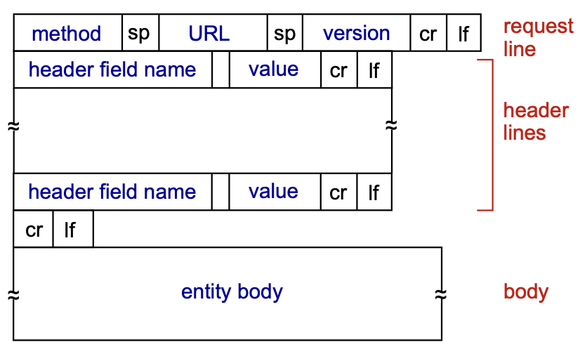
2.1.3 HTTP messages
There are two types of http messages:
- request
- response
the message format is ASCII.
HTTP request messages
HTTP request message general format:
There are multiple possible request messages:
- POST method: web pages often include form input, the user’s input is sent from the client to the server in the body of a HTTP POST request message
- GET method: this is used to send data to a server: the user’s data is included in the URL field of a HTTP GET request message, following a ’?’ (
www.site.com/subdomain?userdata) - HEAD method: this is used to request only the headers, without any objects, it is used during implementation
- PUT method: this uploads a new object to the server, completely replacing the file that exists at the specified URL with the content in the body of the POST HTTP request message
HTTP response messages
Structure of a HTTP response message:
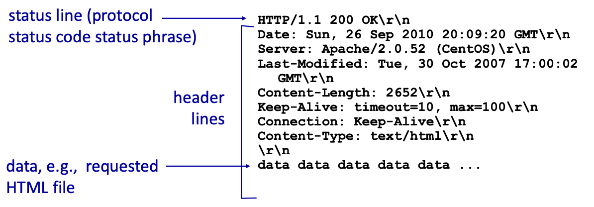
2.1.4 Status Codes
The status code appears in the first line in the server-to-client response message, there are multiple status codes for http responses:
- 200 → Ok : request succeeded, the requested object is included later in this message
- 301 → Moved Permanently : the requested object got moved, new location is specified later in the message with the tag
Location - 400 → Bad Request : request message not understood by the server
- 404 → Not Found : the requested document was not found on this server
- 505 → HTTP version not supported
2.1.5 TELNET
Telnet is a client-server application protocol that provides access to virtual terminals of remote systems on local area networks (LANs) or the Internet.
It is a protocol for bidirectional 8-bit communications. Its main goal was to connect terminal devices and terminal-oriented processes.
Example
telnet <host> <port> cli command open a tcp connection to the specified url and port
type GET <url> HTTP/1.1 to make a get request then press enter
type Host: <host> and press enter twice so have the response
2.1.6 Cookies (2.2.4)
Cookies are used by some browsers to maintain some state between transactions (HTTP is stateless).
The Cookies mechanism can be divided in four components:
- Cookie Header Line in http response message
- Cookie Header Line in the next http request message
- Cookie File kept on the user’s end system
- Back-End Database at the Web site
- The client makes a simple http request to a server
- The server creates and ID for the user and creates an entry in the backend database for that ID
- The server includes a cookie with this new ID in the response message to the client
- The client store this cookie in a cookie file, stored and managed by the browser
- The next time that same client will make a HTTP request to that same server, it will include this cookie in the cookie header line of the request message
- The server receiving this request message with this cookie will now be able to identify the client and offer extra functionality bounded to this new kind of statefulness
Cookies have various implementations:
- Authorizations
- Shopping Carts
- Recomendations
- User session state (web e-mail)
The question is How do we keep the state?
- protocol endpoints: maintain state at sender/receiver over multiple transactions
- cookies: HTTP messages carry the state
- Cookies permit the sites to learn (a lot) about you on their site.
- Third party persistent cookies allow common identity to be tracked across multiple web sites.
2.1.7 Web Caches (proxy servers) (2.2.5)
Goal: satisfy client request without involving origin server
Why: to alleviate the load on origin servers. Caches are closer to clients so it reduces response time. Caches also alleviate the load on internet as a whole.
The user configures the browser to point to a web cache.
- if the objects is in the cache: the cache returns the object to th client.
- if the object isn’t in cache: the cache asks and receives the object from the origin server, caches it and sends it to client.
Proxy servers act both as a client and as a server. They are typically installed by ISPs.
Problem of recency of cached objects
What do we do if the object is updated on the remote servers and the proxy server isn’t aware?
Conditional GET:
Goal: don’t send an object if the cache already has an up-to-date version.
- Cache: the cache when sending the GET statement includes the version of the cached copy:
if-modified-since:<date> - Server: response contains no object if the cached copy is up to date:
http/1.0 304 Not Modified.
Otherwise, if the object has been updated, the new version is included in the HTTP response:HTTP/1.0 200 OK <data>.
This way the object is only sent if necessary, keeping the stress on the link low.
2.1.8 Important updates
HTTP 1.1
This version introduced multiple pipelined GETs over a single TCP connection.
In this versione the scheduling algorithm for GET requests is FCFS: first come first served.
Issue: small objects may wait for bigger (slower) objects (requests) (HOL blocking: Head of line blocking).
Also loss recovery (retransmitting lost TCP segments) stalls object transmission.
HTTP 2
RFC 7540, 2015: The key goal for this version was decreasing delay in multi-object HTTP requests.
Increased the flexibility for servers when sending objects to clients: objects are divided into frames and the frame transmission is interleaved.
Frames are scheduled to mitigate HOL blocking: smaller frames get sent first.
The order of transmission of requested object is now based on client-specified object priority, not necessarily FCFS.
Problems: recovery from packet loss still stalls transmission, also no extra security over vanilla TCP connections.
HTTP 3
The key goal for this version was to decrease delay in multi-object HTTP requests:
Adds:
- security
- per object error (and congestion) control (more pipelining) over UDP
2.2 E-mail, SMTP, IMAP (2.3)
The e-mail infrastructure is made of these three major components:
- user agents: the user reading, composing and editing mail messages
- mail servers: these have a mailbox containing incoming messages for the user and a message queue of outgoing (to be sent) messages
- simple mail transfer protocol (SMTP)
The E-Mail protocol is described in RFC(5321).
It uses TCP to reliably transfer email messages from clients (mail server that initiates the connection) to servers, port 25. It essentially is a direct transfer from the sending server (acting as a client) to the receiving server.
The transfer is divide in 3 phases:
- handshaking (greeting)
- transfer of messages
- closure
This is command/response interaction, like http:
- commands: ASCII text
- response: status code and phrase
The messages must be in 7-bit ASCII.
2.2.1 Sending Emails
- User composes email
- sends email to his email server
- the client side of SMTP server opens a TCP connection with the destination user’s server
- email is sent over the tcp connection
- destination user can access the email via his email server
2.2.2 Sample SMTP interaction
S: 220 hamburger.edu
C: HELO crepes.fr
S: 250 Hello crepes.fr, pleased to meet you
C: MAIL FROM: <alice@crepes.fr>
S: 250 alice@crepes.fr... Sender ok
C: RCPT TO: <bob@hamburger.edu>
S: 250 bob@hamburger.edu ... Recipient ok
C: DATA
S: 354 Enter mail, end with "." on a line by itself
C: Do you like ketchup?
C: How about pickles?
C: .
S: 250 Message accepted for delivery
C: QUIT
S: 221 hamburger.edu closing connection
2.2.3 Comparison SMTP-HTTP
- HTTP: pull
- SMTP: push
- both have ASCII command/response interaction, status codes
- SMTP uses persistent connections
- SMTP requires the message (header and body) to be in 7-bit ASCII
- SMTP server uses CRLF.CRLF to determine end of message
2.2.4 Mail message format
The format of e-mail messages is specified in RFC 531 (defines protocol) and RFC 822 (defines syntax).
- header lines:
- To:
- From:
- Subject:
blank line- body: the message, 7-bit ASCII characters only
2.2.5 Mail access protocols (2.3.4)
SMTP defines delivery and storage of e-mail messages to the receiver’s server.
We need a way to retrieve e-mails from our mail server: a mail access protocol like IMAP (Internet mail access protocol, RFC 3501).
IMAP defines how messages are stored on the server and provides retrieval, deletion and folders of stored message on the mail server.
We also use HTTP to access web-based interfaces (like gmail, hotmail ecc) that work on top of SMTP (to send e-mails) and IMAP (or POP) (to retrieve e-mails).
POP: Post Office Protocol
POP3 is an extremely simple MAP (mail access protocol), defined in RFC 1939.
POP3 begins when the user agent begins a TCP connection with the mail server, on port 110.
The server accepts the connection and the protocol now processes through 3 phases: authorization, transaction, and update.
- authorization: the user agent sends a username and a password (in the clear) to authenticate the user. To do this the user uses two commands:
user: <username>andpass: <password> - transaction: the user agent retrieves messages and issues commands: mark messages for deletion, remove deletion marks, and obtain mail statistics. Commands:
list,retr,dele,quit - update: occurs after the client has issued the quit command, ending the POP3 session. At this time, the mail server deletes the messages that were marked for deletion.
A user agent using POP3 can be configured by the user to adhere to one of two modes: download-and-keep and download-and-delete.
In a POP3 transaction, the user agent issues commands, and the server responds to each command with a reply.
There are two possible responses: +OK (sometimes followed by server-to-client data), used by the server to indicate that the previous command was fine; and -ERR, used by the server to indicate that something was wrong with the previous command.
A POP3 server only holds some state in a single session, like the list of marked messages, it does not hold state between sessions, this greatly simplifies the implementation of this protocol.
POP servers also do not offer any kind of message managing functionality, no folders and such.
IMAP
To solve this and other problems, the IMAP protocol, defined in RFC 3501, was invented. Like POP3, IMAP is a mail access protocol. It has many more features than POP3, but it is also significantly more
complex.
An IMAP server will associate each message with a folder; when a message first arrives at the server, it is associated with the recipient’s INBOX folder.
The recipient can then move the message into a new, user-created folder, read the message, delete the message, and so on.
The IMAP protocol provides commands to allow users to create folders and move messages from one folder to another.
IMAP also provides commands that allow users to search remote folders for messages matching specific criteria.
Another important feature of IMAP is that it has commands that permit a user agent to obtain components of messages. For example, a user agent can obtain just the message header of a message
or just one part of a multipart MIME message. This is useful in low-bandwidth situations.
Note that an IMAP server holds state between sessions.
2.3 The Domain Name System (DNS) (2.4)
Problem: internet hosts and routers have both
- an IP address (IP), used for addressing datagrams
- a “name”, used by humans (like www.google.com)
How do we map between IP address and name, and vice versa?
solution: the DNS
The Domain Name System (DNS) is a distributed database implemented in a hierarchy of many name servers.
It is an application-layer protocol: hosts and name servers communicate to resolve names (address-name translation), this keeps the complexity at the network’s edge.
Registering a subdomain means linking it univocally to an IP address, registering it in the DNS database.
2.3.1 ICANN
The distributed DNS server is managed by Internet Corporation for Assigned Names and Numbers (ICANN), which also defines what the top layer domains* are.
2.3.2 DNS services (2.4.1)
- hostname to IP address translation
- host aliasing:
- alias names for the canonical hostname
- mail server aliasing
- load distribution: replicated web servers: many IP addresses correspond to one name. When a client ask for the resolution for a hostname, the DNS server answers with the whole list of associated IP addresses, but each time in a different order, since the client normally goes for the first in the list.
2.3.3 DNS structure
The DNS is a distributed, hierarchical database:
- ROOT: the client queries the root DNS server to find the IP address of the Top level domain’s DNS server
- TOP LEVEL DOMAIN: the client queries the top level domain DNS server to find the address of the authoritative DNS server
- AUTHORITATIVE: the client queries the authoritative DNS server to find the IP address for the desired link.
A distributed structure was chosen because a centralized DNS:
- doesn’t scale
- is a single point of failure (SPF)
- cannot be near every host
- cannot handle that much traffic volume (Comcast DNS servers serve 600B DNS queries per day)
- cannot be easily maintained
ROOT name servers
These servers are the official contact-of-last-resort for name servers that cannot resolve the queried name.
These are extremely important internet function, internet couldn’t function without it. DNSSEC provides security: authentication and service integrity.
The are 13 logical root name servers worldwide, each server is replicated many times (there are more than 200 root name server in the US alone).
TLD name servers
These servers are the ones responsible for resolving every top level domain (.com, .org, ecc) and every Country Code Top Level Domains (CCTLDs) (.it, .uk, ecc).
For example:
- Network Solutions is the authoritative registry for .com and .net TLDs
- Educause is the authoritative registry for the .edu TLS
- Registro.it is the authoritative registry for the .it CCTLD
Authoritative DNS servers
These servers are the organizations’ own DNS server(s), providing authoritative hostname-to-IP mappings for the organization’s name hosts.
These can be maintained by the organization or a service provider.
Local DNS name servers
Also called default name servers, these are installed into each ISP and they act as a sort of proxy DNS server, they have a local cache of recent name-to-address translations pairs, BUT it may be out of date!
When a host makes a DNS query it is sent to its local DNS server.
Local DNS servers use the user-server paradigm, but use UDP connections.
2.3.4 Name resolution Approaches
Iterated Query
The host first asks the local DNS server, which in turn contacts every required DNS server until resolution, the contacted servers reply with the name of the server to contact and the local DNS server executes.
When the local DNS server has resolved the name, it replies to the host with the answer.
This approach is better.
Recursive Query
The host first asks the local DNS server, which in turn contacts the next server (the root), which then asks the next (TLD) eccetera, until resolution.
Every contacted server asks the next, in a chain of queries and answers, until the authoritative server has the answer, at this point every server replies with the answer down the chain, until it arrives to the host.
More load on the servers, apart from the local DNS servers.
2.3.5 DNS records (2.4.3)
Once a name server learns a mapping, it caches it. Caches entries timeout and disappear after some time (TTL).
Typically local name servers cache TLD servers mapping, as to put less stress on root name servers.
Cached entries may be out-of-date, this is a best-effort name-to-address translation: if a hostname changes IP address, it may not be know Internet-wide until all TTLs expire.
The DNS is a distributed database storing resource records (RR):
RR format: (name, value, type, ttl)
- type=A (address)
- name is a hostname
- value is the associated IP address
- type=NS (name system)
- name is domain (what you enter in the search bar)
- value is the hostname of the authoritative name server for this domain
- type=CNAME (“canonical name”)
- name is an alias name for some “canonical” name (the real name)
- value is the canonical name for the alias
- type=MX
- value is the name of the mailserver associated with
name
- value is the name of the mailserver associated with
- there are even more types
2.3.6 DNS protocol messages
DNS query and reply messages use the same format:
- message header:
- identification: 16 bit number (ID) for query, reply uses the same number
- flags:
- query or reply
- recursion desired
- recursion available
- reply is authoritative
| ← 2 bytes → | ← 2 bytes → |
|---|---|
| identification | flags |
| # questions | # answer RRs |
| # authority RRs | # additional RRs |
| questions (4 bytes) | .. |
| answers (4 bytes) | .. |
| authority (4 bytes) | .. |
| additional info (4 bytes) | .. |
nslookup: command-line tool to discover the IP address or DNS record of a specific domain name |
2.3.7 Inserting Records into DNS
- register the name (name.topleveldomain) at the DNS registrar* (e.g. Network Solutions)
- provide names and IP addresses of the authoritative name server (both primary and secondary)
- registrar inserts NS and A records (RRs) into the TLD (top level domain) server
- create the authoritative server locally with the IP address inserted into the TLD
2.3.8 example of DNS resolution
Requesting host (alice.iet.unipi.it) asks the local DNS server what the IP for www.networkutopia.com is.
Local DNS server contacts the root DNS server, which replies with the IP of the .com DNS server.
Local DNS server now contacts the .com DNS servers, which replies with the IP of the authoritative server for networkutopia.com.
Now the local DNS server contacts the authoritative server, which replies with the information needed, which is now rooted back towards the initial client with finally a reply to the requesting host.
2.3.9 DNS security
DNS servers are susceptible to:
- DDoS attacks
- not successful to date against root servers
- Redirect attacks
- man-in-the-middle: intercepting DNS queries
- DNS poisoning: sending false replies to the DNS servers, which then get cached
- exploit DNS for DDoS
- spoofing the source IP address of DNS requests so they appear to come from the victim’s IP. When DNS servers respond, they send the (much larger amplification) replies to the victim, overwhelming it with traffic.
DNSSEC
Redirect Attacks and Exploit DNS for DDoS are accounted for in DNSSEC: domain name system security extensions are a set of extension that add security to the DNS protocol. This works by signing with crypted signatures the DNS records. This guarantees the authenticity and integrity of the replies.
3 P2P applications (2.5)
Every peer looks more like a powerful client from the Client-Server paradigm, technically every peer is on the same level.
The availability of resources this way is not guaranteed from a powerful server, but from the sheer number of peers → self scalability.
There isn’t an always on server.
End systems arbitrarily communicate with each other.
Peers request service from other peers, providing service to other peers in return.
Indexes are needed for mapping information to the right host locations.
3.1 Content Indexes
Indexes are needed for mapping information to the right host locations.
A content index is a Database with (key,value) pairs.
- key is the content type
- value is the IP address
The peers query the database with the key and the database replies with values that match the key.
Peers can also insert pairs.
3.1.1 Centralized Index
This is a service provided by a server (or a server farm).
When a user becomes active, the application notifies the index with its IP address and a list of available files.
The files are distributed by peers, but the search is client-server style: Hybrid Approach
Drawbacks:
- single point of failure
- performance bottleneck
- copyright problems
This is the system used by Napster, a P2P system for music sharing.
3.1.2 Query Flooding
This is a completely decentralized approach.
When searching for one item, a peer starts querying other peers, which in turn contact other “neighbors” (flooding), until one sends the item to the original peer searching for it.
The file download is done from a single peer.
Limited-scope query flooding: query flooding with a predetermined, limited number of hops (scope).
- it reduces the query traffic and therefore congestion.
- but decreases the probability to locate the content.
- limited-scope: the query flooding stop at a certain “level” of subquery (for example each query starts with , the peers receiving it decrement it and sends it over and again, until )
It is possible to plot a Overlay Network: a graph formed of all active peers as nodes and the TCP connection among them as edges.
This system was used in the original Gnutella version (LimeWire).
3.1.3 Hierarchical Overlay
This approach is a middle ground between centralized and completely decentralized.
Not all peers are equal, Super Nodes (SN) exist, these are peers with high bandwidth and high availability.
SN have local indexes: peers inform their SN about content they have available, and SNs form an SN overlay net.
Peers ask their local SN where they can find an item, SN responds with the IP of the peer with the item, or, if the item is not in the local index, the SN asks other SNs, until the item is found.
Again the file download is done from a single peer.
Used in modern Gnutella.
3.1.4 Distributed Hash Table (DHT)
non serve saperlo per l’esame
This is a distributed P2P database.
Used in BitTorrent.
3.2 How much time does it take to distribute one file to N peers?
- Server upload capacity:
- Peer upload capacity:
- max upload rate (limiting max download rate) is
- Peer download capacity:
- minimum client download rate:
- file size:
time to distribute in client-server approach:
the first component scales linearly with .
time to distribute in peer-to-peer approach:
if we suppose , we have .
So client-server scales linearly with , and instead peer-to-peer tends to a limited number.
3.3 BitTorrent
The file that needs to be transferred gets divide into 256Kb chunks, and the peers in the torrent send and receive these chunks.
Torrent: group of peers exchanging chunks of a file.
tracker: node that tracks peers participating in the torrent.
Torrent Server: server that knows the IPs of the trackers.
Peers may discover other peers by trackers, DHT (distributed hash table), or PEX (peer exchange).
Chunks don’t even get transferred sequentially, every chunk has an ID so the entire file gets rebuilt by the asking peer once every chunk has arrived.
While a peer is download chunks it also upload already downloaded chunks then, when it has every chunk, it may leave or remain in the torrent.
3.3.1 Entering a Torrent
- Alice contacts the torrent Server and gets the IP of the tracker.
- Alice contacts the tracker and asks to be included in the torrent.
- The tracker adds Alice to the list of peers participating to the torrent and then sends the list to Alice.
- Alice tries to open TCP connections with every peer in the list.
- Alice manages to open TCP connections with only a subset of the torrent list, the peers she manages to connect with are called neighbors. Peers are divided in leeches (ones who don’t have a complete copy of the file), seeders (ones who have every chunk) and free-riders (who only want to download the file, not seed the file).
- Alice asks now her neighbors what chunks they have.
- Alice asks first for the rarer chunks, the ones that are scarse in the “neighborhood”. This approach is called rarest first.
- Now that Alice has some chunks, other neighbors ask her for chunks, she now has to choose which neighbors to send the chunks to. She now adopts the tit for tat approach, she starts with sending the data to the 4 neighbors sending her chunks at the highest rate.
- Other peers are choked by Alice.
- Alice re-evaluates the top 4 peers every 10 seconds.
- Every 30 seconds Alice randomly selects another peer for sending to: she “optimistically unchokes” this peer. This new peer may also join the top 4.
4 Video streaming and content distribution networks (2.6)
The video stream traffic is the major consumer of internet bandwidth.
Content Distribution services are responsible for 80% of residential ISP traffic (data from 2020).
Two challenges:
- how do we scale to ~1 billion users?
- heterogeneity: different users have different capabilities
The solution is distributed, application-level infrastructure.
4.1 Images
An image is an array of pixels, where each pixel is represented by bits.
4.2 Video
A video is a sequence of images displayed at a constant rate (framerate), normally 24,25 or 30 images per second.
4.3 Coding
We can use redundancy within and between frames to decrease the number of bits used to encode the image.
- spatial coding: instead of sending values of the same color, just send the color and the number if times it repeats ().
- temporal coding: instead of sending the complete frame, just send the differences from the frame
Also video encoding rate can be:
- CRB (constant bit rate)
- VRB (variable bit rate): the video encoding rate changes as the amount of spatial and temporal coding changes
Examples of compression standards:
- MPEG1 (CD-ROM): 1.5 Mbps
- MPEG2 (DVD): 3-6 Mbps
- MPEG4 (often used in internet): 64Kbps - 12 Mbps
NOT to be confused with “MPEG4 part 14”, aka “MP4”, which is the container format
MPEG stands for Moving Picture Experts Group, a collection of standards developed by SO/IEC for audio and video coding.
Note: coding and encoding here are synonyms.
4.4 Challenges of streaming
- server-to-client bandwidth will vary over time.
- packet loss and delay will also vary over time.
- continuous playout constraint: once the client’s playout begins, playback must match the original timing.
In an ideal world the servers send one frame every 1/30th of a second, the user receives one frame at the same interval, with a fixed network delay, and displays the frames at the correct framerate.
Network delay though is variable! Solution: clients stores the received frames (client-side buffering) and displays them at the correct framerate with a client playout delay.
4.5 Compression
An important characteristic of video is that it can be compressed, trading quality with lower file sizes.
Today we have algorithms that can compress videos to any desired bit-rate, the higher the bitrate the higher the quality and the overall user viewing experience.
Compressed video typically ranges between 100 kbps to over 10 Mbps for 4k streaming. This amounts to a huge amount of traffic and storage: a single 2 Mbps video of a duration of 67 minutes will consume 1 GB of storage and traffic ().
In order to provide continuous playout, the network must provide an avera end-to-end throughput to the streaming application that is at least as large as the desired bitrate for the video.
We can use compression to create and store the same video at different bitrates, so that the streaming application (user) can choose which one to request based on the internet throughput it knows can achieve.
4.6 HTTP streaming (2.6.2)
The video is simply stored at an HTTP server as an ordinary file with its URL. When an user wants that video, it establishes a TCP connection with the server and issues an HTTP GET request for that URL.
The server then sends the video file within an HTTP response message, as quickly as the network allows.
On the client side the bytes are buffered, once the number of collected bytes achieve a predetermined threshold, the client application begins playback:
the streaming application gets the bytes from the streaming buffer, decompresses them into frames, and plays them back at the right framerate on the user’s screen, all while continuing to receive new information (the video) from the server.
This way of streaming has worked well but it has a shortcoming: every user receives the same video, independently from its network capability.
4.6.1 Dynamic Adaptive Streaming over HTTP (DASH) (2.6.2)
In DASH the video gets stored on the server at different bitrates (every version is a different file so it has a different URL), the streaming application dynamically chooses chunks of a few seconds of the video in whatever bitrates it deems adequate.
The HTTP server has a manifest file, which provides an URL for each version of the video along with its bitrate.
- The client requests the manifest file
- the client requests a chunk of the video at a desired bitrate
- while downloading the chunk the client measures the received bandwidth and runs a rate determination algorithm to select the chunk to request next.
4.7 Content Distribution Networks (CDNs) (2.6.3)
How do content providers offer content to millions of users?
For a content provider the simplest approach would be to just build a single capable server, but this has many drawbacks (single point of failure, popular media sent many times over the same network, congestion ecc), thereby the applied strategy is to build servers all around the world, that sort of act like proxies, in which they store the most requested files in their area of operation.
The user asks the generale server where it can find the file and the server redirects it to a server near the client which has that piece of media stored. If there is no such server near the client, CDNs utilize the PULL approach: the main server will quickly send the media to one of the servers accessible by the client, who will then download the file from the latter. When a server is full it removes the less frequently requested files.
There are two different approaches:
- Enter deep: building many servers and incorporate them near access ISPs, improving user perceived delay and overall user experience.
- Bring home: building many servers but less than the previous approach and employing them near IXPs. This results in lower maintenance needed compared to “enter deep”, but higher average latency and more congestion.
4.7.1 Netflix Case Study
- Information regarding Netflix account is stored on the Netflix registration and accounting servers.
- The user browses the Netflix catalog, which is stored on Amazon cloud.
- These Amazon cloud servers upload copies of the multiple versions of these videos to the DAHS CDN servers
- When the user asks the Amazon cloud servers for a piece of content, the servers return the manifest file for it.
- The user’s machine contacts the correct DASH CDN server and the streaming begins