- 1 Ethernet Hubs
- 2 Link Layer Switches
- [[#2 Link Layer Switches#2.1 Ethernet Switch|2.1 Ethernet Switch]]
- [[#2.1 Ethernet Switch#2.1.1 Multiple Simultaneous Transmissions|2.1.1 Multiple Simultaneous Transmissions]]
- [[#2.1 Ethernet Switch#2.1.2 Switch Forwarding Table|2.1.2 Switch Forwarding Table]]
- [[#2.1 Ethernet Switch#2.1.3 Self-Learning|2.1.3 Self-Learning]]
- [[#2.1 Ethernet Switch#2.1.4 Frame filtering and forwarding|2.1.4 Frame filtering and forwarding]]
- [[#2 Link Layer Switches#2.1 Ethernet Switch|2.1 Ethernet Switch]]
- 3 Switched Networks
- [[#3 Switched Networks#3.1 Interconnecting Switches|3.1 Interconnecting Switches]]
- [[#3 Switched Networks#3.2 Switches vs Routers|3.2 Switches vs Routers]]
- [[#3 Switched Networks#3.3 Example of a small institutional network|3.3 Example of a small institutional network]]
- [[#3 Switched Networks#3.4 Datacenter Networks|3.4 Datacenter Networks]]
- 4 Virtual LANs (VLANs)
- [[#4 Virtual LANs (VLANs)#4.1 Port-based VLANs|4.1 Port-based VLANs]]
- [[#4 Virtual LANs (VLANs)#4.2 MAC address-based VLANs|4.2 MAC address-based VLANs]]
- [[#4 Virtual LANs (VLANs)#4.3 VLANs distributed on multiple switches|4.3 VLANs distributed on multiple switches]]
- [[#4.3 VLANs distributed on multiple switches#4.3.1 802.1Q VLAN frame format|4.3.1 802.1Q VLAN frame format]]
- 5 Packet Switched Wire-Area Networks (WANs)
- [[#5 Packet Switched Wire-Area Networks (WANs)#5.1 Types of Service|5.1 Types of Service]]
- [[#5.1 Types of Service#5.1.1 Connectionless|5.1.1 Connectionless]]
- [[#5.1 Types of Service#5.1.2 Connection|5.1.2 Connection]]
- [[#5 Packet Switched Wire-Area Networks (WANs)#5.1 Types of Service|5.1 Types of Service]]
- 6 Link Virtualization
uni
As we have seen, broadcast networks have limited coverage, let’s see how we can build an expansible network.
1 Ethernet Hubs
Ethernet hubs (“bus box”) are physical-layer “dumb” repeater:
bits coming in one link go out all other links at the same time.
- All the nodes connected to the hub can collide with one another.
- no frame buffering
- no CSMA/CD (CD) at the hub: host NICs must detect collisions
2 Link Layer Switches
2.1 Ethernet Switch
The switch is a link layer device, so it takes an active role: it stores and forwards ethernet frames.
- it examines the incoming frame’s MAC address and selectively forwards the frame to one or more outgoing links, if the frame is to be forwarded on the segment.
- it uses CSMA/CD to access the segment
- switches are transparent: the hosts are unaware of the presence of the switches
- switches are plug-and-play and self-learning
2.1.1 Multiple Simultaneous Transmissions
Every switch has a dedicated direct connection to the switch.
The switches buffer the packets.
The ethernet protocol is used on each incoming link, so the are no collisions and full duplex is supported: each link is its own collision domain.
All of this means that on a single switch there can be simultaneous transmissions (as long as every host included in said transmissions is in only one transmission).
2.1.2 Switch Forwarding Table
Each switch has a switch table, where each entry contains:
- MAC address of host
- interface to reach host
- time stamp
Sort of like a routing table. !
2.1.3 Self-Learning
We said the switch is self-learning, because it learns which hosts can be reached through which interfaces:
- when a frame is received, the switch learns the location of the sender
- it records the sender/location pair in the switch table
2.1.4 Frame filtering and forwarding
When a frame is received at the switch:
- records incoming link and MAC address of the sending host
- indexes the switch table using the MAC destination address
- if the entry is found for the destination:
if the destination is on the segment from which the frame arrived then drop the frame.
else forward the frame on the interface indicated by the entry
else flood (forward on all interfaces except the arriving interface)
3 Switched Networks
3.1 Interconnecting Switches
These self learning switches can be interconnected together by another “higher level” switch.
3.2 Switches vs Routers
- Both are store-and-forward:
- routers are network-layer devices, so they examine the network-layer headers
- switches are link-layer devices, so the examine link-layer headers
- both have forwarding tables:
- routers compute tables using routing algorithms and IP addresses
- switches learn the forwarding tables using flooding and learning MAC addresses
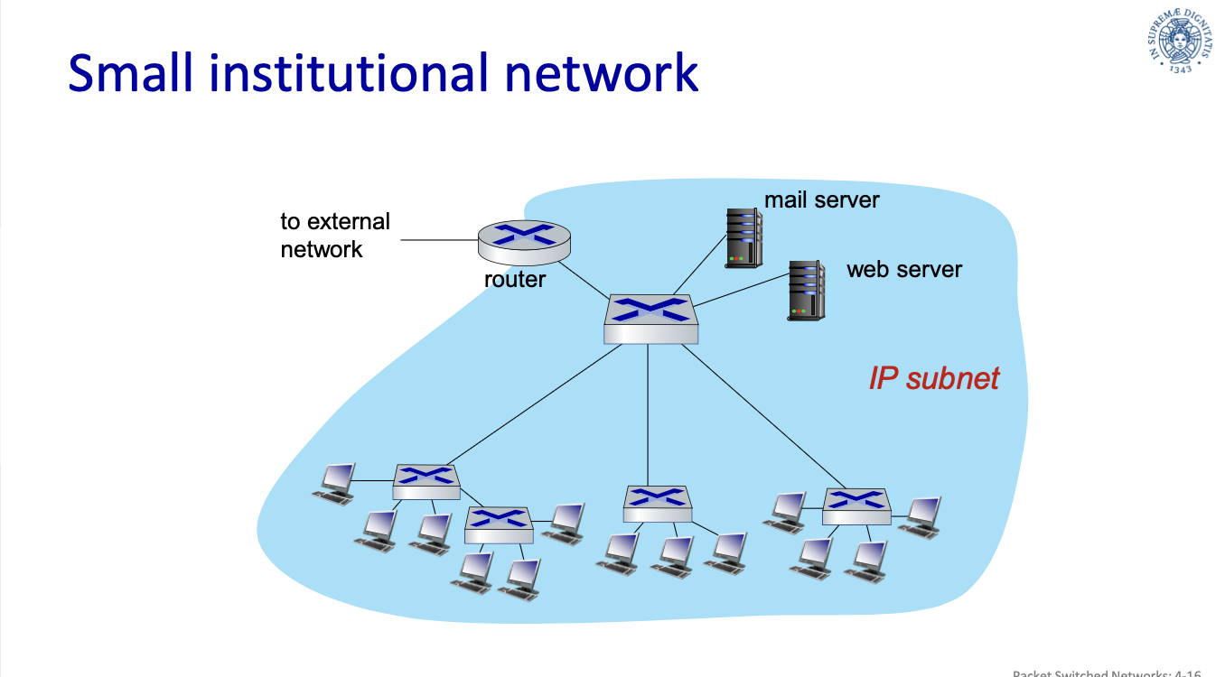
3.3 Example of a small institutional network
I server sono nella zona demilitarizzata, gli host comuni sono nella zona militarizzata
small institutional network:
3.4 Datacenter Networks
Datacenters are thousands of host in close proximity, that are not intended for use of clients, at least, not directly.
Datacenter networs, top to bottom:
- Border routers:
- tier-1 switches: connect to ~16 Tier-2 switches below
- tier-2 switches: connect to ~16 TORs below
- Top of Rack (TOR) switchs: one switch per rack and connect to blades with 40-100Gbps ethernet
- Server Racks: 20-40 server blades, these are the hosts
4 Virtual LANs (VLANs)
With the solution proposed above, instead of a single point of collision, we have a single broadcast domain: every layer-2 broadcast traffic (ARP, DHCP, unknown MAC) must cross the entire LAN.
As LAN (local are network) sizes grow we get efficiency, security and privacy issues.
How can we limit the broadcast to a subsection of a LAN?
Do we give each subsection a dedicated switch? But subsections can be of very different sizes.
4.1 Port-based VLANs
The solution is VLANs, which are and work as LANs but are separated from physical LAN.
The ports of the switches are grouped by the switch management software so that a single physical switch operates as multiple virtual switches.
Switches supporting VLAN capabilities can be configured to define multiple virtual LANs over a single physical LAN infrastructure.
- Traffic Isolation: frames to/from ports of a VLAN can only reach ports from that VLAN.
- dynamic membership: ports can be dynamically assigne among VLANs
- forwarding between VLANs: this is done via routing, just like with separate switches
- in practice vendors sell combined switches plus routers
4.2 MAC address-based VLANs
It is also possible to define VLANs based on MAC address.
4.3 VLANs distributed on multiple switches
A Trunk Port carries frames between VLANs defined over multiple physical switches.
These frames can’t be normal 802.1 frames, they must carry VLAN ID info.
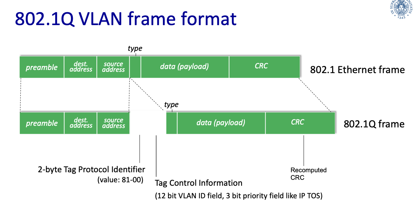
4.3.1 802.1Q VLAN frame format
The 802.1q protocol adds/removes additional header fields for frames forwarded between trunk ports.
5 Packet Switched Wire-Area Networks (WANs)
Nodes get identified through a unique address similar to the ethernet MAC address.
The internet core is no longer a hierarchical structure, but switches form a mesh, this leads to expandability and we get rid of the SPF.
This way there are multiple routes from/to hosts, how do we find the best route?
5.1 Types of Service
These are the types of service a network can offer:
5.1.1 Connectionless
(even the switched version of ethernet)
- each packet is managed on an individual basis
- also known as datagram service
- packets do not arrive in order
Datagram Service
This is a no-call setup and there is no concept of connection.
The packets between the same source-destination pari may take different paths.
Packets are forwarded using the destination of the host address.
Forwarding Table
| MAC address | Interface | TTL |
|---|---|---|
| Destination Address Range | Link Interface |
|---|---|
| 11001000 00010111 00010000 00000000 Through 11001000 00010111 00010111 11111111 | 0 |
| … | … |
| otherwise | 3 |
- TTL: Traceroute
5.1.2 Connection
- a virtual circuit is preliminarily established
- all packets follow the same path
- packets arrive in order
Virtual Circuit
A virtual circuit is a source-to-destination path.
It behaves like a telephone circuit.
==call setup, teardown for each call before data can flow ????==
Procedure:
- sender: initiate call
- receiver: incoming call
- r: accept call
- s: call connected
- s: data flow begins
- r: receive data
Implementation
A virtual circuit consists of:
- path from source to destination
- VC numbers, one number for each link along path
- entries in forwarding tables in the routers (or switches) along the path
A packet belonging to a VC carries the VC number, rather than the destination address.
The VC number can be changed on each link and the new VC number comes from the forwarding table
Forwarding table
Structure of a forwarding table in a switch.
| Incoming interface | incoming VC # | outgoing interface | outgoing VC # |
|---|---|---|---|
| … | .. | .. | .. |
| The switches maintain the information on the connection state. |
6 Link Virtualization
The path from the source to destination is regarded as a point to point virtual link, thus the service type (5.1 Types of Service) is not relevant from the Internet point of view.